



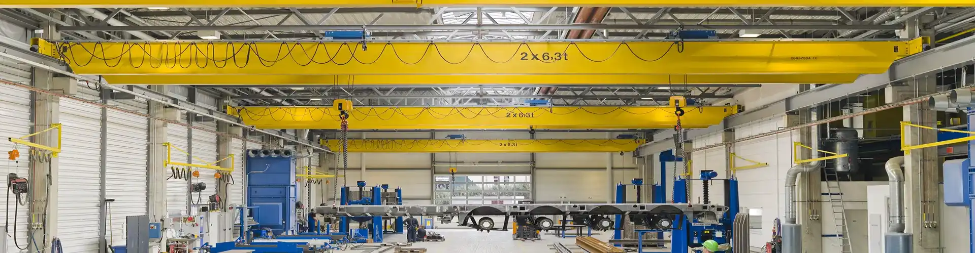
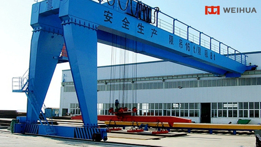
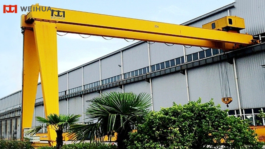
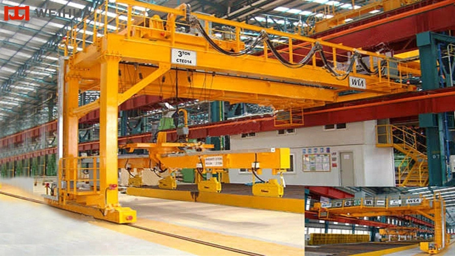
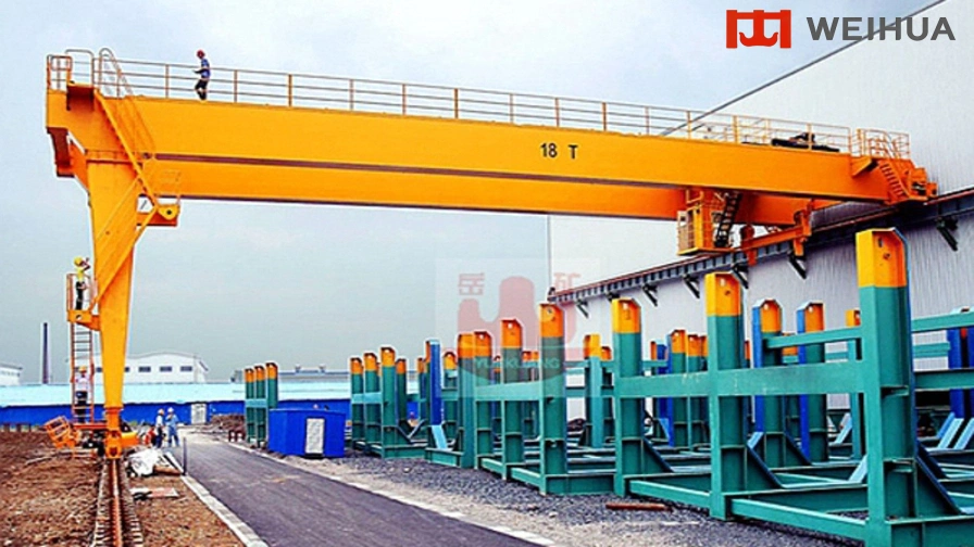


Semi-gantry cranes are a specialized branch of overhead lifting equipment. The double girder semi-gantry crane adopts an asymmetric supporting structure: one side is equipped with A-shaped supporting legs travelling on ground rails, while the other side is fixed to factory or warehouse building walls.
This innovative structural combination significantly improves space adaptability, making the equipment highly flexible for outdoor material handling and confined-area hoisting applications. It provides an efficient lifting solution where traditional overhead cranes cannot fully utilize available installation space.
Girder Structure Classification & Performance
Truss Girder
Fabricated by welding angle steel or I-beam steel, the truss girder features low manufacturing cost, lightweight structure and excellent wind resistance. However, it contains more welding joints, resulting in relatively larger deflection, lower structural rigidity and reduced operational reliability. It is mainly suitable for light-load working conditions with standard safety requirements.
Single Box Girder
Formed by integral welding of steel plates, the box girder provides high structural rigidity and safety performance, making it suitable for medium and large-tonnage lifting operations. Its disadvantages include higher manufacturing costs, heavier self-weight and relatively weaker wind resistance compared with truss structures.
Double Box Girder
The double box beam structure delivers outstanding lifting capacity, ultra-wide span coverage and excellent overall stability, making it ideal for heavy-duty industrial applications. Compared with single-girder cranes of the same lifting capacity, its self-weight is slightly higher, providing stronger structural bearing capability and improved operational stability.
Safety Protection Configuration
The crane is equipped with a complete set of standardized safety protection devices to ensure stable, reliable and secure operation:
Overload limiting protection device
Impact-resistant long-life polyurethane buffer assemblies
Travelling limit switches for stroke control
Voltage loss and phase sequence fault protection system
Emergency stop cutting-off device
Lifting height limit protector
| Crane operate mechanism | Travelling speed (m/min) | 20 | 30 | |
| Reduction ratio | 58.78 | 39.38 | ||
| 58.95 | 39.42 | |||
| motor | type | ZDY21-4 | ||
| Power (kw) | 2x0.8 | |||
| Revolving speed(r/min) | 1380 | |||
| Lifting mechanism (electric hoist) and travelling mechanism | Model | CD1, MD1 | ||
| Lifting speed (m/min) | 8(7)/8/0.8(7/0.7) | |||
| Lifting height (m) | 6, 9, 12, 18, 24, 30 | |||
| Travelling speed (m/min) | 20, 30 | |||
| Motor | Conical squirrel-cage | |||
| Work duty | A3-A5 | |||
| Power source | 3 phase 50Hz 380V | |||
| Wheel diameter | ∅270mm | |||
| Orbital width | 37-70mm | |||
